
Gear Honing & Powder Metallurgy Oil Filtration
Gear honing and cutting, and powder-metallurgy pressing and sintering, run on oils that must stay clean for high-pressure supply and tight dimensional control. Fine metal and abrasive particles are the main threat. Centrifugal separation removes them continuously without consuming media.
This page covers one application direction in detail: where the contamination comes from, what the fluid and solids actually are, how centrifugal separation behaves in that context, and what has to be confirmed before a machine is specified.
In short
- Typical solids: steel and cast-iron fines, abrasive grit (CBN, alumina, SiC), metal powder, oxide scale and soot — removed by density difference, with no filter medium to replace.
- It complements magnetic separation: the magnet takes ferrous fines, the centrifuge also captures non-magnetic abrasive and soot.
- The JY-N95 covers 25–120 L/min with 2200 G rated acceleration and automatic solids discharge; the working flow rate depends on the fluid.
- No micron rating or efficiency figure is published. The cleanliness target of the downstream system is confirmed by test on your fluid.
What Makes This Application Difficult
Where the contamination comes from
- Honing and gear cutting generate fine steel and abrasive particles that stay suspended in the cutting oil.
- Powder-metallurgy operations produce fine metal powder carry-over in pressing, and dust and debris in sintering and finishing circuits.
- Quenching oils accumulate oxide scale, soot and polymerised residue.
Fluid characteristics
- Cutting and honing oils are formulated for extreme pressure and are often viscous; quenching oils are heated and oxidise over time.
- Hydraulic systems supplied from the same circuit are sensitive to fine particles that accelerate valve and pump wear.
Where conventional filtration falls short
- Fine filter elements load quickly and are replaced frequently, with the associated cost and downtime.
- Magnetic separation captures ferrous particles but not abrasive or oxide material.
- Settling tanks do not remove the fine fraction that circulates with the oil.
Effect on production
- Fine particles damage high-pressure pumps, valves and nozzles, causing unplanned downtime.
- Contaminated oil leaves marks and dimensional deviation on honed gear flanks.
- Quench-oil contamination changes cooling curves and distorts metallurgical results.
Solids, Fluid and Operating Conditions
Qualitative characterisation — the actual range for your process is established from fluid samples and operating data, not assumed from this table.
| Particle / solid | Density difference | Typical size | Solid concentration | Fluid viscosity | Temperature & chemistry |
|---|---|---|---|---|---|
| Steel and cast-iron fines | High (magnetic) | Micron to sub-millimetre | Rises with stock removal | Oil, medium to high | Reactive; promotes oil oxidation |
| Abrasive grit (CBN, alumina, SiC) | Moderate to high (non-magnetic) | Micron range | Wheel-dependent | Oil, medium to high | Inert; highly abrasive |
| Oxide scale and soot (quench oil) | Moderate to high | Fine | Rises with throughput | Heated oil | Oxidised; may polymerise |
Density difference, size class and loading vary by process. Absolute values are confirmed during application evaluation.
Honing Oil, Powder-Metallurgy Circuits and Quench Oil
The page covers three different duties. They share the need for clean oil but differ in what the solids are, how the fluid behaves and what the separator can and cannot correct.
| Aspect | Gear honing and cutting oil | Powder-metallurgy circuits | Quench oil |
|---|---|---|---|
| Dominant solids | Fine steel and cast-iron fines; abrasive grit (CBN, alumina, SiC) from the honing tool | Fine metal powder carry-over; dust and debris in sintering and finishing circuits | Oxide scale, soot and polymerised residue |
| Fluid | Extreme-pressure oil, thin to viscous depending on grade; may share a high-pressure supply with hydraulics | Pressing lubricant and finishing oils; limits set by the process step and atmosphere | Heated oil that oxidises over time |
| Role of a magnet | Removes ferrous fines cheaply; abrasive grit passes | Depends on the powder; non-ferrous powders are not magnetic | Limited; soot and polymerised residue are not magnetic |
| Outside what separation corrects | Depletion of dissolved additives | Powder close to the fluid density separates only partially | Oxidation, water ingress and polymerised residue |
| Data to collect first | Solids content, abrasive type, particle-size distribution, downstream cleanliness target | Powder type and size distribution; where it must not go | Operating temperature, solids and soot level, oxidation indicators, cooling-curve requirement |
Qualitative comparison. Fluid and solids data for your own circuit replace this table at evaluation.
How Centrifugal Separation Applies
Centrifugal separation concentrates dense particles at the bowl wall under the JY-N95's rated 2200 G and discharges them automatically, so the circulating oil is cleaned continuously while the machine keeps running. It complements magnetic separation: the magnetic step removes ferrous material cheaply, while the centrifuge also captures non-magnetic abrasive and oxide particles that magnets miss.
For powder-metallurgy circuits the duty is defined by what the powder is and where it must not go — pressing lubricant, sintering atmospheres and finishing oils each impose different limits. Because separation depends on density difference, fine powder that sits close to the fluid density may not separate completely, and that limit is established by test rather than by promise.
In practice the two stages are designed together: the magnet and screen take the bulk of the coarse and ferrous load, and the centrifuge works on the fine fraction. The next section sets out which variables decide how far that fine fraction is removed.
- No micron rating is published for the JY-N95. Fine-solids targets are confirmed against verified test evidence for the actual fluid.
- Particles with little density contrast against the oil separate slowly; pre-thickening or a different stage may be required.
- Quench-oil condition is also affected by oxidation and water ingress, which centrifugal separation does not correct.
What Governs Separation: Density, Size and Viscosity
Settling under centrifugal acceleration follows Stokes' law for ideal particles in laminar flow. It does not predict site results, but it shows which variable to look at first and which way each one pushes.
| Factor | Effect on settling speed | What it means for this application |
|---|---|---|
| Density difference | Settling is faster when the difference between solid and oil is larger | Steel, CBN, alumina and SiC have a large density contrast against oil and separate more readily; soot and polymerised residue sit closer to the oil density and separate more slowly. |
| Particle diameter | Settling slows sharply as particle diameter falls | Micron-range abrasive and fines are the limiting fraction; the achievable cut is established by test on the actual fluid. |
| Oil viscosity | Settling is slower in more viscous oil | Thin honing oils favour faster separation; viscous cutting oil and heated quench oil change with temperature. |
| Acceleration | Higher acceleration increases settling speed | Set by the machine (2200 G rated). The operating levers are throughput and temperature. |
| Residence time | Longer residence gives more time to settle | Lower throughput increases residence time within the 25–120 L/min range. |
Direction of effect only. Real oils, particle shapes and concentrations deviate from the ideal case; absolute values are confirmed on your fluid.
Where the Separator Sits in the Circuit
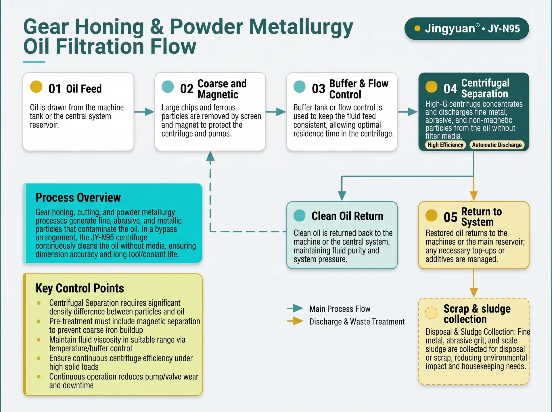
Swipe to see all steps.
- 1
Oil feed
Oil is drawn from the machine tank or the central system reservoir.
- 2
Coarse and magnetic pre-treatment
Large chips and ferrous particles are removed by screen and magnet.
- 3
Centrifugal separation
Fine non-magnetic and ferrous particles concentrate at the bowl wall.
- 4
Automatic discharge
Solids are discharged as a compact cake while feed continues.
- 5
Return to system
Cleaned oil returns to the machine or high-pressure supply circuit.
Representative arrangement. Piping, buffer volume and control integration are confirmed per project.
Cleanliness Targets and What the Separator Is Evaluated Against
The reason to clean the oil is usually downstream: pumps, valves, nozzles and the finished surface. The target therefore comes from the system, not from the separator.
Start from the downstream requirement
- Take the cleanliness requirement from the pump, valve and nozzle manufacturers; it is commonly stated as an ISO 4406 code.
- Take the surface-finish and dimensional requirement from the honing or forming process.
- For quench oil, take the cooling-curve and cleanliness requirement from the heat-treatment specification.
How the separator fits
- It lowers the circulating fine-solids load continuously; it is not a filtration rating and no micron rating is published.
- Whether the target is met is confirmed by test on the actual fluid.
- Where the target is tighter than the separation delivers, a final polishing filter remains in the design and carries a lower solids load.
From Fluid Sample to Machine Specification
Evaluation is a short, defined sequence. The same parameters are measured before and after so the result is a comparison on your own circuit.
Before: establish the baseline
- Sample the circulating oil at operating temperature, not from the tank bottom.
- Record viscosity, solids content, particle type and size distribution, and the particle-count code if one is used.
- Note the abrasive type and wheel or stone specification, magnet and filter cleaning intervals, and any pump or valve wear history.
- For quench oil, record temperature, oxidation indicators, water content and the cooling-curve check.
After: trend in your circuit
- Repeat the same measurements at fixed intervals under the agreed throughput and temperature.
- Follow filter changeout frequency, pump, valve and nozzle condition, honed-surface quality and cooling behaviour.
- Adjust one variable at a time and keep the record.
- Judge the benefit from the trend in your circuit, not from a general figure.
Where a bench or pilot test is needed, the conditions are agreed after the engineering review of your data.
Practical Notes for Running the Circuit
Pre-treatment
- A coarse screen and a magnet take chips and ferrous fines out before the separator.
- Clean the magnet on a routine; a heavily loaded magnet passes fines downstream.
- The separator is intended for the fine fraction that remains in circulation.
Quench oil and hot-oil safety
- Set the processing temperature with the quench-oil supplier.
- Hot-oil handling, flash point and fire protection are reviewed as part of the project.
- Oxidation and water are managed by the quench-oil programme, not by the separator.
Central systems
- Size from the total flow and solids load of all machines on the reservoir.
- Do not mix oil grades between honing, cutting and hydraulic circuits.
- Buffer volume and piping are confirmed per project.
Handling the discharged cake
- The cake is oil-wetted and contains metal fines, abrasive and oxide; handle it as oily industrial solid waste under local regulations.
- Keep it oil-wetted in storage and avoid creating dry dust during handling.
- Confirm the waste classification and disposal route with the local authority or waste contractor.
Symptoms and What to Check
Separation addresses the solids part of these problems. Each symptom also has process causes that sit outside the separator.
| Symptom | Possible contributor | What to check |
|---|---|---|
| Pump, valve or nozzle wear in the high-pressure circuit | Fine solids circulating in the oil | Solids content and particle size at the pump inlet, downstream cleanliness target, pre-treatment |
| Marks or dimensional deviation on honed flanks | Abrasive grit and fines in the honing oil | Abrasive in the circulating oil, oil flow and temperature, filtration stage |
| Magnet loads very quickly | High ferrous fine load or high stock removal | Magnet cleaning interval, upstream solids load, separator throughput |
| Quench cooling behaviour drifts | Scale, soot, oxidation or water in the oil | Solids, oxidation indicators, water content, quench-oil programme |
| Fine filter elements still change often | Solids still reaching the filter, or the wrong filter grade | Upstream solids, separator throughput, filter specification |
| Oil darkens or smells burnt | Oxidation of heated oil | Operating temperature, ferrous fines, oil change interval |
General guidance. Root cause is confirmed against your process data.
Confirmed Parameters — Not Marketing Figures
Values are drawn from the product parameter set used across this site. Nothing is restated or re-typed per application page.
| Flow rate | 25–120 L/min Depends on fluid properties and operating conditions — the maximum rate is not available for every medium. |
|---|---|
| Centrifugal acceleration | 2200 G An acceleration parameter — not a filtration precision. |
| Motor power | 4.0 kW |
| Power supply | 380 V, 50 Hz |
| pH range | 6–9 Applicability confirmed per fluid chemistry — not a universal compatibility statement. |
| Control system | PLC, fully automatic PLC brand options: SIEMENS / ABB / SCHNEIDER — optional configurations, confirmed per order. |
| Solids discharge | Automatic |
| Inlet connection | DN20 Standard configuration; confirm against order documentation. |
| Outlet connection | DN100 (4 in) Standard configuration; confirm against order documentation. |
| Operating design | Continuous 24-hour operation design Design intent; duty cycle and maintenance interval confirmed with the configuration. |
Check Whether Your Duty Fits the Range
The selection tool runs the same six checks our engineers run: flow range, fluid and material compatibility, settling behaviour, viscosity and temperature, pretreatment needs, and the resulting suitability class. Your industry is carried into the form automatically.
Run the selection check
The selection tool compares your flow rate, fluid chemistry and solids data against the confirmed operating range of the JY-N95 and returns one of four classifications. It does not promise separation efficiency.
Engineering Questions for This Application
Is a centrifuge needed if magnetic separation is already installed?
Can it protect a high-pressure coolant system?
Does it work for quenching oil?
What about powder-metallurgy powder carry-over?
How is maintenance planned?
What data is needed for evaluation?
What cleanliness level can be reached?
Is a downstream filter still needed?
Can one machine serve a central system with several honing machines?
How does thin honing oil behave in the separator?
Can it process hot quench oil?
How should the separated cake be handled?
Have a Fluid That Fits This Description?
Send the fluid type, solids loading and target — our engineers review the duty and confirm what has to be tested.