
Optical Glass & Technical Ceramics Grinding Fluid
Cutting, grinding, lapping and polishing of optical glass and technical ceramics generate fine, hard, non-magnetic powder. Filter paper either tears or blinds within hours, and the fine fraction that escapes settles everywhere in the circuit. Centrifugal separation removes it by density, without a medium.
This page covers one application direction in detail: where the contamination comes from, what the fluid and solids actually are, how centrifugal separation behaves in that context, and what has to be confirmed before a machine is specified.
In short
- Typical solids: glass powder, technical-ceramic powder and lapping or polishing abrasive — non-magnetic, hard and abrasive, separated by density rather than by a filter medium.
- The limiting case is the very fine tail near colloidal size, which settles slowly whatever the field; there the separator is a pre-clarification step.
- The JY-N95 covers 25–120 L/min with 2200 G rated acceleration and automatic solids discharge; the working flow rate depends on the fluid.
- No micron rating or clarification percentage is published. The result is confirmed on your actual slurry.
What Makes This Application Difficult
Where the contamination comes from
- Glass and ceramic grinding produces fine powder across a wide size range, including a fraction finer than one micrometre that stays suspended.
- Lapping and polishing slurries add abrasive compounds whose density and chemistry differ from the workpiece material.
- Non-magnetic solids defeat magnetic separation, and the fines are abrasive to pumps and seals.
- Cutting, edging, drilling and chamfering each release a different particle-size band, while polishing adds cloth- or wheel-borne debris to the same circuit.
Fluid characteristics
- Water-based coolants and slurry vehicles are common; concentration and additive package change settling behaviour.
- Fine powder raises slurry viscosity and holds the abrasive in suspension longer, which is desirable at the tool but harmful in the return circuit.
Where conventional filtration falls short
- Filter paper and cartridges tear or blind rapidly under the abrasive load, creating media cost and downtime.
- Hydrocyclones recover only the coarse cut and leave the fines to build up.
- Settling tanks require long residence times and large footprints, and the fine fraction often does not settle at all.
Effect on production
- Recirculating fines scratch polished surfaces and cause cosmetic rejects in optical parts.
- Abrasive solids accelerate wear of pumps, valves and seals.
- High suspended solids reduce cooling performance and shorten coolant life.
Solids, Fluid and Operating Conditions
Qualitative characterisation — the actual range for your process is established from fluid samples and operating data, not assumed from this table.
| Particle / solid | Density difference | Typical size | Solid concentration | Fluid viscosity | Temperature & chemistry |
|---|---|---|---|---|---|
| Glass powder | Moderate — above water, below most metals | Finer than 1 µm to sub-millimetre | High in generating and smoothing operations | Water-like to slightly thickened | Mildly alkaline in water; leaches silicates |
| Technical ceramic powder (alumina, zirconia, SiC) | Moderate to high | Micron and finer than 1 µm | Process-dependent | Suspension-forming | Chemically inert; highly abrasive |
| Lapping and polishing abrasive | High (e.g. diamond, alumina, ceria) | Finer than 1 µm to micron | High in polishing slurry | Slurry | Vehicle-dependent; may need pH control |
Density difference, size class and loading vary by process. Absolute values are confirmed during application evaluation.
Cutting, Grinding, Lapping and Polishing
Each stage releases a different particle band into a different fluid. The separation duty is set by the stage, not by the material alone.
| Stage | Dominant solids | Fluid | Separation consideration |
|---|---|---|---|
| Cutting, edging, drilling and chamfering | Coarser glass or ceramic chips and powder | Water-based coolant | A coarse screen or settling chamber goes first; the separator works on the fine remainder |
| Generating and smoothing | High concentration of powder across a wide size range, including a fine tail | Water-based coolant | Main bypass duty; concentration and the fine tail set throughput |
| Lapping | Abrasive compound plus workpiece powder | Slurry | Define whether the slurry is reused before setting the separation target |
| Polishing | Fine abrasive (for example ceria, alumina or diamond) plus near-colloidal powder, cloth or wheel debris | Slurry, often reused deliberately | Separation sorts by size and density and can change the abrasive distribution; pH control may need checking against the confirmed 6–9 range |
Qualitative comparison. Fluid and solids data for your own line replace this table at evaluation.
How Centrifugal Separation Applies
Glass and ceramic powders are denser than the aqueous vehicle, so a centrifugal field concentrates them at the bowl wall. The JY-N95's rated 2200 G accelerates settling of the fine fraction that stays suspended in a tank. Because the mechanism does not depend on a pore size, the abrasive and non-magnetic nature of the powder does not degrade the separation the way it degrades filter media.
The practical difficulty is the very fine tail: particles close to colloidal size settle slowly regardless of the field, and the density contrast for some glass compositions is modest. In those cases the circuit is designed with a buffer tank, a defined residence time or a polishing stage, and the achievable clarification is established by test on the actual slurry.
The consequence is that clarification is designed in stages: coarse interception, a buffer with a defined residence time, the separator, and where the target demands it a further polishing stage. The next section sets out how density, size and concentration act on settling.
- Very fine fractions settle slowly. Where the target requires removal of colloidal material, centrifugal separation is a pre-clarification step, not a complete solution.
- No micron rating or clarification percentage is published; the achievable result is confirmed on the actual slurry.
- Abrasive solids wear pumps, piping and the machine itself. Materials of construction and wear-part intervals are confirmed with the configuration.
What Governs Separation: Density, Size and Concentration
Settling under centrifugal acceleration follows Stokes' law for ideal particles in laminar flow. It does not predict site results, but it shows which variable to look at first.
| Factor | Effect on settling speed | What it means for this application |
|---|---|---|
| Density difference | Settling is faster when the difference between solid and fluid is larger | Glass has the smallest density contrast against water and ceria the largest; compositions closer to the fluid density separate more slowly. |
| Particle diameter | Settling slows sharply as particle diameter falls | The finest near-colloidal tail is the limiting fraction; the achievable cut is established by test on the actual slurry. |
| Acceleration | Higher acceleration increases settling speed | Set by the machine (2200 G rated). The operating levers are throughput and concentration. |
| Solids concentration | High concentration hinders settling and thickens the slurry | Generating and smoothing circuits carry high solids; throughput is set lower and a coarse stage is placed ahead. |
| Colloidal behaviour | Brownian motion and surface charge keep the finest particles dispersed | Near colloidal size the field does little; agglomeration by pH adjustment or a flocculant can be evaluated where the process allows. |
| Residence time | Longer residence gives more time to settle | Lower throughput within the 25–120 L/min range increases residence time. |
Direction of effect only. Real slurries, particle shapes and concentrations deviate from the ideal case; absolute values are confirmed on your fluid.
Where the Separator Sits in the Circuit
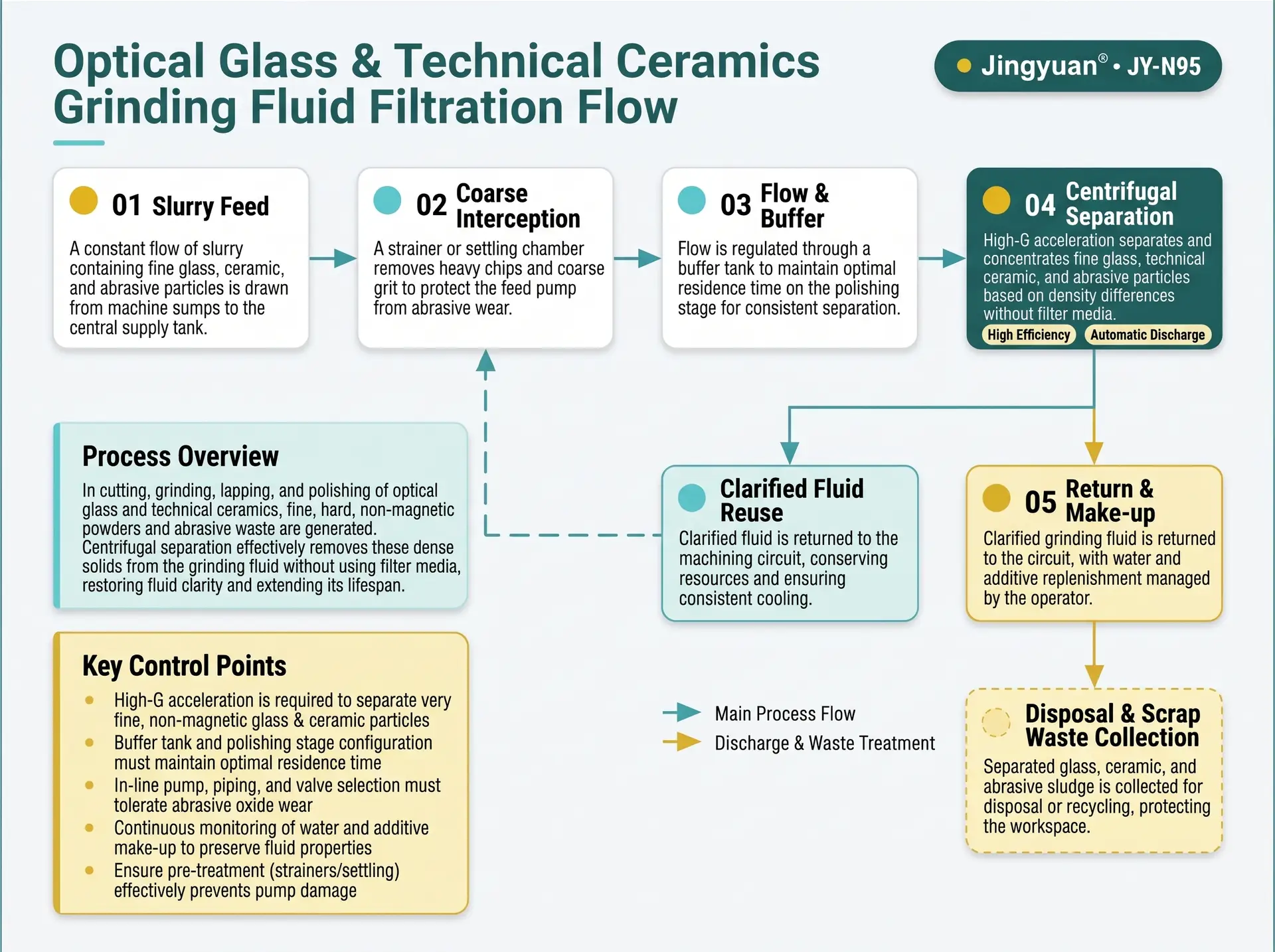
Swipe to see all steps.
- 1
Slurry feed
Coolant or slurry is drawn from the machine sump or the central supply tank.
- 2
Coarse interception
A screen or settling chamber removes coarse chips and protects the feed pump.
- 3
Centrifugal separation
Fine glass or ceramic powder is concentrated at the bowl wall.
- 4
Automatic discharge
Solids leave as a low-moisture cake for collection.
- 5
Return and make-up
Clarified fluid returns to the circuit, with water and additive make-up controlled by the operator.
Representative arrangement. Piping, buffer volume and control integration are confirmed per project.
Handling the Fine Tail
Because the finest fraction settles slowly, the circuit around the separator matters as much as the machine.
Buffer and residence time
- A buffer tank gives the feed a stable concentration and a defined residence time.
- Lower throughput lengthens residence time and improves capture of the fine fraction.
- Buffer volume and piping are confirmed per project.
Staged clarification
- Place a coarse screen or settling chamber ahead of the separator.
- Where the surface-quality target needs colloidal material removed, plan a further polishing stage after the separator.
- Define the clarity target from the surface-quality requirement first.
Agglomeration where permitted
- pH adjustment or a flocculant can be evaluated for the fine tail.
- Additives must be compatible with the coolant, the surface quality and the confirmed pH range of 6–9.
- Not every optical process can accept added chemistry.
Central bypass or dedicated unit
- The machine can run in bypass on a central tank or as a dedicated unit on one machine.
- A central tank averages the load of several machines; a dedicated unit isolates one process.
- Control integration is confirmed per project.
From Slurry Sample to Machine Specification
Evaluation is a short, defined sequence. The same parameters are measured before and after so the result is a comparison on your own line.
Before: establish the baseline
- Sample the circulating fluid and record solids concentration, pH, temperature and coolant concentration.
- Measure the particle-size distribution, paying attention to the finest fraction.
- Note the material and abrasive types, additive package and the surface-quality target.
- Record the scratch or cosmetic reject rate, pump and seal wear interval, media consumption and coolant change interval.
After: trend on your line
- Repeat the same measurements at fixed intervals under the agreed throughput.
- Compare the particle-size distribution of the clarified fluid and of the cake to see where the fine tail remains.
- Follow reject rate, wear intervals and coolant life.
- Judge the benefit from the trend on your line, not from a general figure.
Where a bench or pilot test is needed, the conditions are agreed after the engineering review of your data.
Practical Notes for Running the Circuit
Pre-treatment
- A screen or settling chamber retains coarse chips and protects the feed pump.
- Keep return lines arranged so settled solids are not re-suspended into the circuit.
- The separator is intended for the fine fraction that remains in circulation.
Abrasive wear
- Abrasive solids wear pumps, piping and the machine itself.
- Materials of construction and wear-part intervals are confirmed with the configuration.
- Include wear inspection in the routine maintenance plan.
Reusing abrasive
- Separation sorts by size and density, so the cake may differ from the original abrasive distribution.
- Decide whether reuse is intended before setting the separation target.
- Check the size distribution of anything that is returned to a polishing step.
Handling the discharged cake
- The cake is a low-moisture powder; avoid creating dry dust during handling.
- Fine glass, ceramic and abrasive dust can be hazardous when airborne, depending on composition; check the material safety data and applicable exposure requirements.
- Confirm the waste classification and disposal route with the local authority or waste contractor.
Symptoms and What to Check
Separation addresses the solids part of these problems. Each symptom also has process causes that sit outside the separator.
| Symptom | Possible contributor | What to check |
|---|---|---|
| Scratches or cosmetic rejects on polished surfaces | Recirculating fines, oversize particles or pad and cloth debris | Particle-size distribution of the circulating fluid, coarse interception, return-line arrangement |
| Pump and seal wear is high | Abrasive solids in the circuit | Solids concentration at the pump, wear-part condition, materials of construction |
| Fluid is still cloudy after separation | Colloidal fraction, or throughput too high for the size | Particle-size distribution, throughput, buffer and residence time, agglomeration option |
| Cooling performance falls | High suspended solids in the coolant | Solids concentration, bypass flow, coolant concentration |
| Polishing removal rate drifts | Abrasive size or concentration changed in the circuit | Slurry size distribution and concentration, what the separator is removing |
| Settled solids build up in tanks and lines | The fine fraction settles in the circuit | Flow velocity, tank design, bypass draw-off position |
General guidance. Root cause is confirmed against your process data.
Confirmed Parameters — Not Marketing Figures
Values are drawn from the product parameter set used across this site. Nothing is restated or re-typed per application page.
| Flow rate | 25–120 L/min Depends on fluid properties and operating conditions — the maximum rate is not available for every medium. |
|---|---|
| Centrifugal acceleration | 2200 G An acceleration parameter — not a filtration precision. |
| Motor power | 4.0 kW |
| Power supply | 380 V, 50 Hz |
| pH range | 6–9 Applicability confirmed per fluid chemistry — not a universal compatibility statement. |
| Control system | PLC, fully automatic PLC brand options: SIEMENS / ABB / SCHNEIDER — optional configurations, confirmed per order. |
| Solids discharge | Automatic |
| Inlet connection | DN20 Standard configuration; confirm against order documentation. |
| Outlet connection | DN100 (4 in) Standard configuration; confirm against order documentation. |
| Operating design | Continuous 24-hour operation design Design intent; duty cycle and maintenance interval confirmed with the configuration. |
Check Whether Your Duty Fits the Range
The selection tool runs the same six checks our engineers run: flow range, fluid and material compatibility, settling behaviour, viscosity and temperature, pretreatment needs, and the resulting suitability class. Your industry is carried into the form automatically.
Run the selection check
The selection tool compares your flow rate, fluid chemistry and solids data against the confirmed operating range of the JY-N95 and returns one of four classifications. It does not promise separation efficiency.
Engineering Questions for This Application
Can centrifugal separation handle non-magnetic glass powder?
Why does filter paper fail on optical grinding coolant?
Is the separated cake reusable?
What about lapping and polishing slurries?
What data is required for evaluation?
Can the machine be integrated into an existing central system?
Can it clarify grinding fluid to optical-grade cleanliness?
Can it be used to recover polishing abrasive such as ceria?
Is a flocculant needed for the fine fraction?
Is the separated cake a dust hazard?
How does a high solids concentration affect separation?
Does the coolant chemistry limit use?
Have a Fluid That Fits This Description?
Send the fluid type, solids loading and target — our engineers review the duty and confirm what has to be tested.