Waste Oil Regeneration — Centrifugal Pre-Treatment
Waste lubricating and hydraulic oils arrive loaded with gums, carbon black, metal wear debris and water. Downstream membrane and distillation stages are expensive and easily fouled, so the solids have to be taken out early. Centrifugal separation performs that front-end duty — high throughput, continuous discharge, no filter media to consume.
This page covers one application direction in detail: where the contamination comes from, what the fluid and solids actually are, how centrifugal separation behaves in that context, and what has to be confirmed before a machine is specified.
In short
- The duty is protective: removing heavy solids and sludge before membrane and distillation stages, continuously and without filter media.
- It does not dehydrate the oil, remove dissolved oxidation products or restore additives; fine carbon held by dispersants separates only in part.
- The JY-N95 covers 25–120 L/min with 2200 G rated acceleration and automatic solids discharge; throughput for each waste stream is established by test.
- Heating, flash point and free water are safety questions for the train, reviewed per project.
What Makes This Application Difficult
Where the contamination comes from
- Collected waste oil carries high concentrations of gums, carbon black, metal wear particles and tank sludge.
- Solid load varies strongly between collections, so the front-end stage must tolerate a wide and unpredictable inlet condition.
- Water is usually present, partly free and partly emulsified, and it changes the behaviour of the whole train.
Fluid characteristics
- Viscosity is high at ambient temperature and is reduced by heating the oil before separation — typically to a moderate temperature that keeps the fluid pumpable and the separation repeatable.
- Chemistry varies between streams: additive packages, oxidation products and contaminants from mixed sources make each batch different.
Where conventional filtration falls short
- Filter bags and cartridges are consumed at a high rate and produce a large volume of oily hazardous waste.
- Settling alone needs long residence time and large tanks, and it does not remove the fine carbonaceous fraction.
- Skipping the front-end stage transfers the solids downstream, where they blind membranes and foul heat-exchange surfaces.
Effect on production
- Membrane stages lose flux and service life when particulate load reaches them; cleaning cycles shorten and elements are replaced early.
- Distillation equipment fouls on heavy solids, forcing shutdowns, manual cleaning and lost throughput.
- Every tonne of solids not removed early becomes waste to be transported and disposed of, with the associated cost and paperwork.
Solids, Fluid and Operating Conditions
Qualitative characterisation — the actual range for your process is established from fluid samples and operating data, not assumed from this table.
| Particle / solid | Density difference | Typical size | Solid concentration | Fluid viscosity | Temperature & chemistry |
|---|---|---|---|---|---|
| Carbon black and gums | Low to moderate; close to the oil in some fractions | Colloidal to fine particulate | High and variable between batches | High (reduced by heating) | Oxidation products; can agglomerate with water |
| Metal wear debris | High | Micron to millimetre | Batch-dependent | High (reduced by heating) | Catalytic for further oxidation |
| Tank sludge and sediment | High | Agglomerated, coarse | Heavy at the bottom of collection tanks | High | Mixed; may carry water and salts |
Density difference, size class and loading vary by process. Absolute values are confirmed during application evaluation.
What Arrives Depends on the Source
Waste oil is not one fluid. The stream type sets the solids, the water and the safety review, so it is the first thing recorded at evaluation.
| Stream | Typical load | Watch-outs | Data to collect first |
|---|---|---|---|
| Used engine oil | Soot and carbon, metal wear particles, oxidation products, water | Dispersants hold fine carbon in suspension; fuel dilution lowers the flash point | Solids content, particle-size distribution, flash point, water content |
| Used hydraulic and industrial oil | Metal wear debris, oxidation products, some water | Usually narrower variation, but additive packages differ | Viscosity against temperature, solids content, water content |
| Mixed collected waste oil | Everything above in varying proportion, plus unknown contaminants | Batch-to-batch variation; hazardous contaminants must be screened before processing | Samples from several collections; screening results; flash point |
| Tank bottoms and sediment | Coarse sludge, water and salts | Heavy loading; not suited to bulk feed | Settling behaviour, solids and water content; pre-settling and screening plan |
Qualitative comparison. Samples from your own stream replace this table at evaluation.
How Centrifugal Separation Applies
In a regeneration train the centrifugal separator sits after heating and coarse screening and before the membrane and distillation stages. It removes the bulk of the heavy solids continuously: at the JY-N95's rated 2200 G, dense particles and sludge migrate to the bowl wall and are discharged automatically while feed continues, so the front-end stage does not have to be stopped to be cleaned.
The value of that stage is protective rather than finishing. It does not dehydrate the oil, it does not remove dissolved oxidation products and it does not produce a saleable base oil on its own; what it does is keep particulate load away from equipment that is far more expensive to clean. Where the downstream train includes fine membrane stages, the separator also reduces the frequency with which those stages must be taken offline.
Fit is decided in this order: the waste stream and its safety review, the solids and water load, then viscosity, temperature and throughput. The next section sets out how those variables act on separation.
- Centrifugal separation removes particulate solids and heavy sludge. It is not a dehydration, deodorisation or distillation step, and it does not restore additive chemistry.
- Separation efficiency depends on the density difference between the solid and the heated oil. Carbonaceous material close to the oil density separates only partially.
- Throughput for a given waste stream is established by test on that stream. System-level capacity is quoted per project, not as a single-machine figure.
- Hot-oil handling, flash point (including any fuel dilution), free water in the heater and fire protection are reviewed per project; the separator does not reduce those risks.
What Governs Separation: Density, Size, Viscosity and Water
Settling under centrifugal acceleration follows Stokes' law for ideal particles in laminar flow. It does not predict site results, but it shows which variable to look at first.
| Factor | Effect on settling speed | What it means for this application |
|---|---|---|
| Density difference | Speed rises in proportion to the difference between solid and oil | Metal wear debris and tank sludge show a far larger density difference than carbonaceous fines, so they separate readily while carbon close to the oil density separates only in part. |
| Particle diameter and dispersion | Speed rises steeply as particle size increases | Colloidal carbon held by dispersant additives settles very slowly; the removable fraction is established by test. |
| Oil viscosity | Speed falls in proportion to viscosity | Mineral-oil viscosity falls markedly with temperature. Heating is therefore the main lever, limited by flash point and thermal stability. |
| Water | Free water separates differently from the solids; emulsified water does not settle | Free water is partly carried out with the sludge; dehydration is a separate unit operation. |
| Acceleration and residence time | Speed rises with acceleration; lower throughput gives longer residence | Acceleration is set by the machine (2200 G rated); the operating levers are throughput and temperature. |
Direction of effect only. Real oils, particle shapes and loadings deviate from the ideal case; absolute values are confirmed on your stream.
Where the Separator Sits in the Circuit
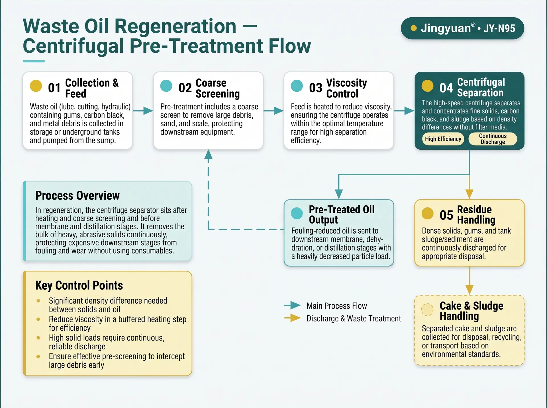
Swipe to see all steps.
- 1
Collection and feed
Waste oil is received, homogenised and pumped from storage.
- 2
Heating and coarse screening
Viscosity is reduced to a defined value and coarse debris is intercepted.
- 3
Centrifugal separation
Heavy solids and sludge are concentrated and continuously discharged.
- 4
Downstream stages
Membrane filtration, dehydration and distillation follow, with a lower particulate load.
- 5
Residue handling
The separated cake is collected as concentrated residue for the appropriate disposal or recovery route.
Representative arrangement. Piping, buffer volume and control integration are confirmed per project.
Protecting the Downstream Train
The separator is a protective stage. Its value is measured in what it keeps away from the equipment behind it.
Heating and placement
- Place the separator close to the heater with insulated or heat-traced piping.
- Hold a defined viscosity at the separator instead of letting the oil cool in the line.
- Heating set point and ramp are confirmed per project.
Feed management
- Homogenise and buffer the feed so inlet conditions change slowly.
- Screen coarse debris; avoid bulk feed of tank-bottom sludge.
- Draw off free water ahead of the heater where possible.
Interface with membrane and distillation
- Define the particulate limit each downstream stage can accept, from the equipment supplier.
- The separator is evaluated against that limit by test; no micron rating is published.
- Control integration with the train is confirmed per project.
Residue route
- The cake is a concentrated residue of solids and oil.
- Decide its collection, classification and destination before commissioning.
- Local waste regulation governs the route.
From Waste-Oil Sample to Machine Specification
Evaluation is a short, defined sequence. The same parameters are measured before and after so the result is a comparison on your own train.
Before: establish the baseline
- Take samples from several collections, not a single batch.
- Record solids content, particle-size distribution, viscosity against temperature, density and flash point.
- Record water content by a laboratory method, and metals or ash where the downstream process needs it.
- Note membrane flux and cleaning frequency, distillation fouling and shutdown interval, and the mass of residue produced.
After: trend in your train
- Repeat the same measurements on the pre-treated oil at fixed intervals under the agreed throughput and temperature.
- Follow membrane flux decline, cleaning-cycle length and distillation run length.
- Compare cake mass and character with the solids removed from the oil.
- Judge the benefit from the trend in your train, not from a general figure.
Where a bench or pilot test is needed, the conditions are agreed after the engineering review of your data.
Practical Notes for Running the Circuit
Hot-oil safety
- Set the heating limit from the flash point of the actual stream, allowing for fuel dilution.
- Free water in hot oil can cause foaming and surging; draw it off first.
- Fire protection and hot-fluid handling are reviewed per project.
Feed variability
- Collections differ; test each waste stream rather than assuming one result.
- Keep a buffer volume so the feed condition changes gradually.
- Record the source of each batch.
Unknown contaminants
- Mixed waste oil can carry hazardous contaminants.
- Screen incoming loads before they enter the train.
- Screening practice follows local regulation and the operator's procedures.
Handling the discharged cake
- The cake is a concentrated residue of solids and oil; classify it by analysis and local regulation.
- Collect it in suitable containers and keep it clear of other waste.
- Confirm the disposal or recovery route with the local authority or waste contractor.
Symptoms and What to Check
Separation addresses the solids part of these problems. Each symptom also has process causes that sit outside the separator.
| Symptom | Possible contributor | What to check |
|---|---|---|
| Membrane flux falls and cleaning cycles shorten | Fine carbon passing the separator | Particle-size distribution of the pre-treated oil, throughput, temperature |
| Distillation equipment still fouls | Residual solids, or thermal degradation in the heater | Solids content downstream, heater temperature, residence time |
| Cake is wet or oily | Viscosity too high, or water in the feed | Temperature, water content, throughput |
| Throughput is lower than expected | High viscosity or high solids loading | Temperature, solids load, feed variability |
| Foaming or surging at the heater | Free water in the hot oil | Water draw-off, heating ramp, feed water content |
| Solids spike between batches | Tank sludge fed in bulk | Collection-tank practice, homogenisation, screening |
General guidance. Root cause is confirmed against your process data.
Confirmed Parameters — Not Marketing Figures
Values are drawn from the product parameter set used across this site. Nothing is restated or re-typed per application page.
| Flow rate | 25–120 L/min Depends on fluid properties and operating conditions — the maximum rate is not available for every medium. |
|---|---|
| Centrifugal acceleration | 2200 G An acceleration parameter — not a filtration precision. |
| Motor power | 4.0 kW |
| Power supply | 380 V, 50 Hz |
| pH range | 6–9 Applicability confirmed per fluid chemistry — not a universal compatibility statement. |
| Control system | PLC, fully automatic PLC brand options: SIEMENS / ABB / SCHNEIDER — optional configurations, confirmed per order. |
| Solids discharge | Automatic |
| Inlet connection | DN20 Standard configuration; confirm against order documentation. |
| Outlet connection | DN100 (4 in) Standard configuration; confirm against order documentation. |
| Operating design | Continuous 24-hour operation design Design intent; duty cycle and maintenance interval confirmed with the configuration. |
Check Whether Your Duty Fits the Range
The selection tool runs the same six checks our engineers run: flow range, fluid and material compatibility, settling behaviour, viscosity and temperature, pretreatment needs, and the resulting suitability class. Your industry is carried into the form automatically.
Run the selection check
The selection tool compares your flow rate, fluid chemistry and solids data against the confirmed operating range of the JY-N95 and returns one of four classifications. It does not promise separation efficiency.
Engineering Questions for This Application
Where should the centrifuge sit in a regeneration train?
Can the separator replace the membrane or distillation stages?
Does it remove water?
How is throughput determined for a waste stream?
What happens to the separated residue?
Is a continuous duty cycle realistic?
What temperature is the oil heated to?
Is free water a concern when heating waste oil?
Can it remove soot and carbon black?
How is the variable inlet condition managed?
Is the separated residue hazardous waste?
Does the separator have to sit directly after the heater?
Have a Fluid That Fits This Description?
Send the fluid type, solids loading and target — our engineers review the duty and confirm what has to be tested.