
Wire Drawing & Tube Drawing Lubricant Filtration
Drawing copper rod, aluminium cable and stainless tube pushes fine metal particles into the lubricant. The oil darkens, odour develops and die wear rises. Centrifugal separation pulls those fines out by density, continuously and without filter media.
This page covers one application direction in detail: where the contamination comes from, what the fluid and solids actually are, how centrifugal separation behaves in that context, and what has to be confirmed before a machine is specified.
In short
- Typical solids: copper, aluminium and steel fines, plus drawing-soap sludge — removed by density, with no filter medium to blind in viscous lubricant.
- Aluminium has the smallest density contrast and separates slowest; copper and steel separate more readily.
- The JY-N95 covers 25–120 L/min with 2200 G rated acceleration and automatic solids discharge; the confirmed pH range is 6–9.
- Dissolved copper, emulsion concentration, pH and microbial control stay with the fluid programme. No micron rating is published.
What Makes This Application Difficult
Where the contamination comes from
- Drawing and tube-drawing generate fine metal wear particles from the workpiece, the die and the mandrel.
- Drawing soap and lubricant residues combine with metal fines to form a sludge that settles in tanks and on heat exchangers.
- Copper and aluminium fines oxidise and act as catalysts for oil degradation and odour formation.
- In mixed shops the same lubricant circuit also serves turning, milling, drilling and washing, where tramp oil from way lubricants and hydraulic leaks adds a second, lower-density phase.
Fluid characteristics
- Drawing oils, emulsion-type lubricants and drawing soaps behave differently in viscosity, wetting and settling behaviour.
- Emulsions are sensitive to metal-ion build-up and to bacterial activity that the fine solids encourage.
Where conventional filtration falls short
- Fine metal particles are hard to intercept without a fine medium, and fine media blind quickly in viscous lubricant.
- Magnetic separators work only for ferrous material and miss copper and aluminium entirely.
- Settling is slow, particularly for the fine fraction that keeps circulating.
Effect on production
- Metal fines abrade the die and the wire surface, degrading dimensional accuracy and surface finish.
- Oxidation products and bacterial growth shorten lubricant life and create odour and skin-irritation problems in the plant.
- Frequent lubricant replacement interrupts production and creates waste.
Solids, Fluid and Operating Conditions
Qualitative characterisation — the actual range for your process is established from fluid samples and operating data, not assumed from this table.
| Particle / solid | Density difference | Typical size | Solid concentration | Fluid viscosity | Temperature & chemistry |
|---|---|---|---|---|---|
| Copper and aluminium fines | High (copper) to moderate (aluminium) | Micron to sub-millimetre | Rises with production volume | Oil, emulsion or soap solution | Non-ferrous; catalytic for oxidation |
| Iron and steel wear particles | High | Micron to coarse | Die and mandrel wear dependent | As above | Magnetic; rusts in aqueous circuits |
| Drawing soap and sludge | Moderate | Flocculated, variable | High in soap-based circuits | High | Alkaline; interacts with hard water |
Density difference, size class and loading vary by process. Absolute values are confirmed during application evaluation.
Drawing Oil, Emulsion and Soap Solution
Drawing lines use three different lubricant families. They differ in viscosity, chemistry and how the separator is reviewed.
| Aspect | Neat drawing oil | Emulsion-type lubricant | Drawing soap solution |
|---|---|---|---|
| Viscosity and settling | Higher viscosity slows migration; temperature control matters | Water-like continuous phase favours faster settling | Viscous, with flocculated sludge |
| Chemistry and biology | Oxidation is catalysed by copper fines | Sensitive to metal ions and to bacterial activity that fines encourage | Interacts with hard water; sludge forms with metal fines |
| pH against the confirmed 6–9 range | Not applicable to neat oil | Checked per product | Often alkaline; may sit above the range, so it is confirmed per fluid |
| Main watch-out | Hot-oil handling and flash point if the oil is heated | Emulsion stability through the pump and separator; foaming | Sludge on tanks and heat exchangers |
| Data to collect first | Viscosity against temperature, particle-size distribution, solids load | Concentration, pH, bacterial status, dissolved metals, solids load | Solution strength, pH, hardness, solids and sludge load |
Qualitative comparison. Fluid and solids data for your own line replace this table at evaluation.
How Centrifugal Separation Applies
Drawing lubricants carry solids with a clear density contrast — copper and steel far above the oil, aluminium moderately so. Under the JY-N95's rated 2200 G the particles migrate outward and concentrate at the bowl wall, and the automatic discharge removes them as a low-moisture cake while feed continues.
Because there is no medium, the circuit is not limited by the blinding that governs fine filter elements in viscous lubricant. The practical constraint moves to viscosity and residence time: heavy oils and emulsions are run at a rate that gives the particles time to migrate, and that rate is established by test on the fluid in use.
Fit is decided in this order: lubricant type and chemistry, the metal and its size distribution, then throughput and temperature. The next section sets out how those variables act on settling.
- Emulsion circuits also need concentration, pH and microbiological control; centrifugal separation addresses the particulate load only.
- Dissolved copper and dissolved salts are not removed. Where they matter, ion exchange or bleed-and-make-up is required.
- Achievable clarification is confirmed per application; no micron rating is published.
- The JY-N95's confirmed pH range is 6–9. Drawing soap solutions and some emulsions run alkaline and may sit above it; pH is confirmed per fluid.
What Governs Separation: Density, Size and Viscosity
Settling under centrifugal acceleration follows Stokes' law for ideal particles in laminar flow. It does not predict site results, but it shows which variable to look at first.
| Factor | Effect on settling speed | What it means for this application |
|---|---|---|
| Density difference | Speed rises in proportion to the difference between solid and fluid | Against mineral oil, copper and steel show a far larger density difference than aluminium, so aluminium fines are the limiting metal. |
| Particle diameter | Speed rises steeply as particle size increases | Micron-range fines are the limiting fraction; finer particles settle much more slowly than coarse ones. |
| Fluid viscosity | Speed falls in proportion to viscosity | Neat oil and soap solutions are more viscous than a water-based emulsion; temperature narrows the gap. |
| Emulsion stability | Shear and chemistry can change how an emulsion behaves | Stability through the pump and separator is checked by test, not assumed. |
| Acceleration and residence time | Speed rises with acceleration; lower throughput gives longer residence | Acceleration is set by the machine (2200 G rated); the operating levers are throughput and temperature. |
Direction of effect only. Real fluids, particle shapes and loadings deviate from the ideal case; absolute values are confirmed on your fluid.
Where the Separator Sits in the Circuit
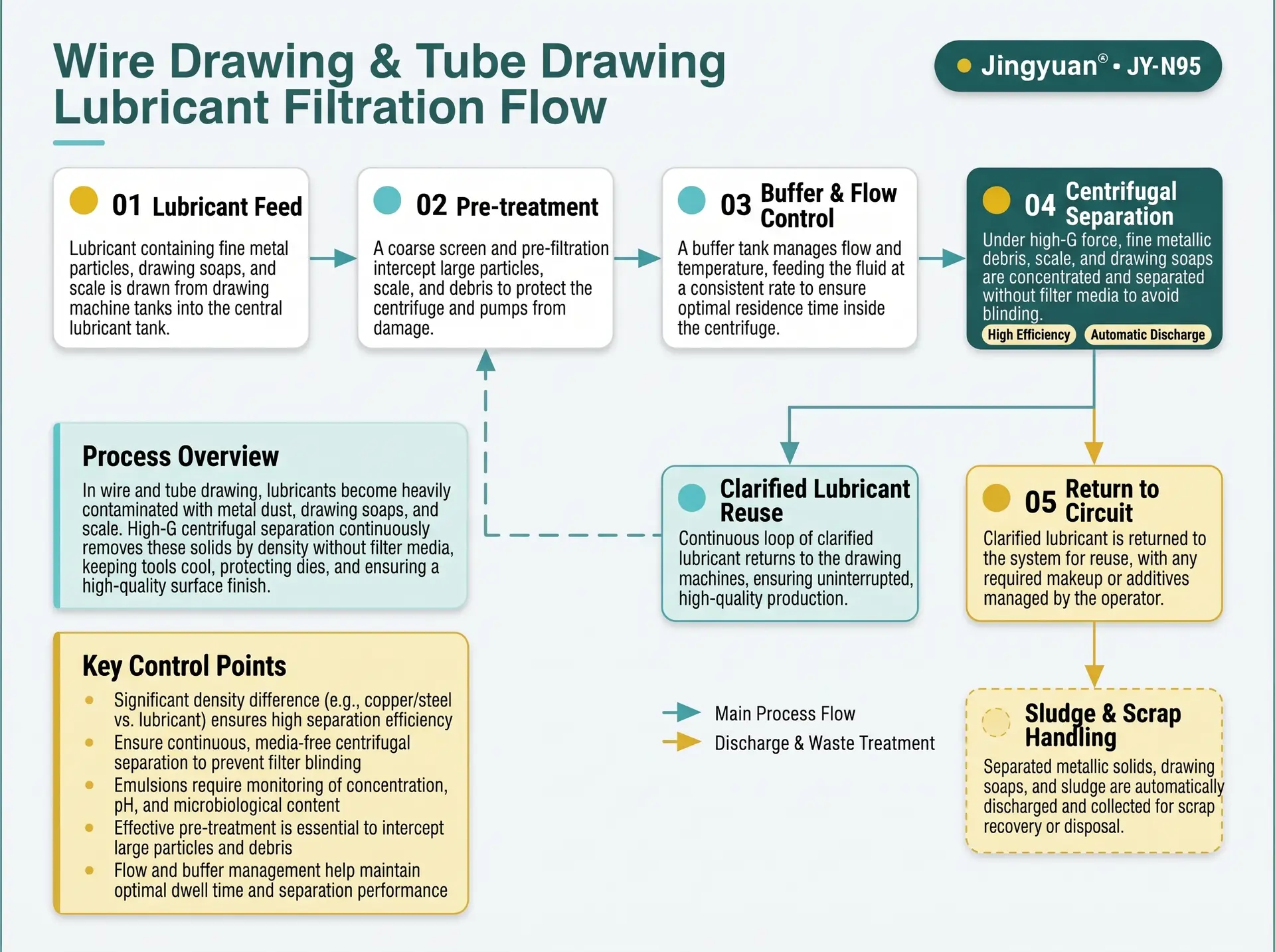
Swipe to see all steps.
- 1
Lubricant feed
Fluid is drawn from the drawing machine sump or the central lubricant tank.
- 2
Pre-treatment
Coarse swarf and tramp material are intercepted; free oil or soap scum is separated where relevant.
- 3
Centrifugal separation
Metal fines concentrate at the bowl wall under centrifugal acceleration.
- 4
Automatic discharge
Solids are discharged as a compact cake for collection.
- 5
Return to circuit
Clarified lubricant returns to the tank, with concentration and level make-up controlled by the operator.
Representative arrangement. Piping, buffer volume and control integration are confirmed per project.
Arranging the Lubricant Circuit
Drawing lines range from a single die box to a central system serving several machines. The arrangement decides how stable the feed is.
Central tank bypass
- Bypass operation on a central tank averages the load of several machines.
- Size from the total flow and solids load; pump, buffer volume and piping are confirmed per project.
- Do not mix lubricant types in one circuit.
Pre-treatment and tramp oil
- A coarse screen keeps swarf out of the machine.
- In mixed shops a skimmer or coalescer deals with tramp oil from way lubricants and hydraulic leaks.
- Free oil and soap scum are separated ahead of the separator where relevant.
Tank design
- Choose a draw-off point that represents the circulating fluid, not the settled sludge layer.
- Avoid quiet zones where soap and metal sludge pile up.
- Include sump and heat-exchanger cleaning in the maintenance plan.
Buffer and flow
- A buffer tank gives a stable feed concentration and a defined residence time.
- Lower throughput lengthens residence time for the fine fraction.
- Control integration is confirmed per project.
From Lubricant Sample to Machine Specification
Evaluation is a short, defined sequence. The same parameters are measured before and after so the result is a comparison on your own line.
Before: establish the baseline
- Sample the circulating lubricant and record solids content, particle-size distribution, viscosity and temperature.
- For emulsions and soap solutions, add concentration, pH, hardness, bacterial status and dissolved copper where it is measured.
- Note the metal drawn, die and mandrel condition and the wire-surface reject rate.
- Record lubricant change interval, tank and heat-exchanger cleaning frequency, odour and operator complaints.
After: trend on your line
- Repeat the same measurements at fixed intervals under the agreed throughput.
- Follow die life, surface rejects, lubricant change interval and sludge build-up.
- Check emulsion stability and concentration after the separator.
- Judge the benefit from the trend on your line, not from a general multiple.
Where a bench or pilot test is needed, the conditions are agreed after the engineering review of your data.
Practical Notes for Running the Circuit
Emulsion care
- Concentration, pH and microbiological control stay with the fluid programme.
- Check emulsion stability through the pump and separator by test.
- Foaming from air entrainment is reduced by a submerged return.
Dissolved metals
- Dissolved copper and salts are not removed by separation.
- Where they matter, plan bleed and make-up or ion exchange.
- Dissolved metals shorten emulsion life even when solids are low.
Shared circuits
- Where one circuit serves drawing, turning, milling and washing, tramp oil and wash chemistry reach the separator.
- Keep wash chemistry out of the drawing circuit.
- Confirm compatibility of every fluid in the circuit before specification.
Handling the discharged cake
- The cake is a low-moisture mass of metal fines wetted with lubricant; handle it as oily industrial solid waste under local regulations.
- Keep it wetted in storage and avoid creating dry dust.
- Segregate by metal if recovery is intended, and confirm the route with the local authority or waste contractor.
Symptoms and What to Check
Separation addresses the solids part of these problems. Each symptom also has chemistry and process causes that sit outside the separator.
| Symptom | Possible contributor | What to check |
|---|---|---|
| Die wear rises or the wire surface is scratched | Fines recirculating in the lubricant | Particle-size distribution of the circulating fluid, die condition, coarse screen, throughput |
| Lubricant darkens | Metal fines, oxidation or bacterial activity | Solids content, temperature, microbial status |
| Odour develops | Microbial activity in aqueous circuits | Bacterial counts, pH, concentration, stagnant zones in the circuit |
| Emulsion splits or creams | Metal ions, pH drift, shear or bacteria | Concentration, pH, dissolved metals, shear in pumps and valves |
| Sludge builds up in tanks and heat exchangers | Soap and metal sludge | Cleaning interval, draw-off location, solids load |
| Lubricant is still dumped often | Dissolved contamination or chemistry drift | Dissolved metals, concentration management, make-up practice |
General guidance. Root cause is confirmed against your process data.
Confirmed Parameters — Not Marketing Figures
Values are drawn from the product parameter set used across this site. Nothing is restated or re-typed per application page.
| Flow rate | 25–120 L/min Depends on fluid properties and operating conditions — the maximum rate is not available for every medium. |
|---|---|
| Centrifugal acceleration | 2200 G An acceleration parameter — not a filtration precision. |
| Motor power | 4.0 kW |
| Power supply | 380 V, 50 Hz |
| pH range | 6–9 Applicability confirmed per fluid chemistry — not a universal compatibility statement. |
| Control system | PLC, fully automatic PLC brand options: SIEMENS / ABB / SCHNEIDER — optional configurations, confirmed per order. |
| Solids discharge | Automatic |
| Inlet connection | DN20 Standard configuration; confirm against order documentation. |
| Outlet connection | DN100 (4 in) Standard configuration; confirm against order documentation. |
| Operating design | Continuous 24-hour operation design Design intent; duty cycle and maintenance interval confirmed with the configuration. |
Check Whether Your Duty Fits the Range
The selection tool runs the same six checks our engineers run: flow range, fluid and material compatibility, settling behaviour, viscosity and temperature, pretreatment needs, and the resulting suitability class. Your industry is carried into the form automatically.
Run the selection check
The selection tool compares your flow rate, fluid chemistry and solids data against the confirmed operating range of the JY-N95 and returns one of four classifications. It does not promise separation efficiency.
Engineering Questions for This Application
Can the separator remove copper and aluminium fines?
What causes lubricant darkening and odour?
Is the machine suitable for emulsion-type drawing lubricants?
How often must the machine be serviced?
Can it run on a multi-machine central system?
What data do you need to evaluate the duty?
Does it separate tramp oil?
Will the separator break my emulsion?
Can it handle drawing soap solutions?
What happens to dissolved copper?
How should the separated cake be handled?
How do I measure the benefit on my line?
Have a Fluid That Fits This Description?
Send the fluid type, solids loading and target — our engineers review the duty and confirm what has to be tested.